Technical Articles
No headings found on this page.
Input Line Chokes for VFD to optimise AHF Sizing
A Variable Frequency Drive is an electro-mechanical drive used to control the speed & torque of AC Motors by varying the input voltage & frequency of the motor. VFDs are widely used in conveyor systems, pumps, blowers, machine tools & other such applications which require variable speed along with variable torque. But a VFD, being a non-linear load, is a source of harmonics in the line.
Solutions for Harmonics Mitigation:
Active Harmonic Filters are the ideal solution for harmonic mitigation. They compensate the harmonics generated by VFD by generating the same harmonic components in the opposite phase. As a result, Power Factor can be maintained close to unity & the supply current will be a pure sinusoidal wave with no harmonic contents.
However, AHFs have a very high cost per ampere if they are used to compensate for the harmonics generated by the VFDs. The sizing of the AHF can be reduced by reducing the harmonic content at the output of the VFD.
Hence input line chokes are used at the output of the VFD. This is an inductor coil which opposes rapid change in current because of its impedance.
Input Line Chokes will:
Important Note:
Measuring CTs should not be used for protection purposes, and vice versa. Always select CTs based on the intended application.
Understanding Accuracy Classes:
Accuracy classes are typically 0.2, 0.2s 0.5, 0.5s, or 1.0, indicating very precise measurement at rated current.
Applicable standards: Class 1 as per IEC 62053-21 C Class 0.5, 0.5S, 0.2, 0.2S as per IEC 62053-22.
The “s” in 0.2s and 0.5s denotes special accuracy, especially at low current levels. Refer the below table for better understanding.
| Accuracy class | Meaning | Max. Error at Rated Current |
|---|---|---|
| 0.2s | Very high precision - low currents | ±0.2% (better at lower currents) |
| 0.2 | Very high precision | ±0.2% |
| 0.5s | Special high-precision class | ±0.5% (better at lower currents) |
| 0.5 | High precision | ±0.5% |
| 1.0 | Standard precision | ±1.0% |
Key Parameters for CT Selection:
1. CT Accuracy Class
Choose a CT with an accuracy class equal to or better than the DPM’s class.
2. Burden (VA Rating)
3. Rated Primary Current
4. Rated Secondary Current

Advantage of Site selectable CT / PT in DPM
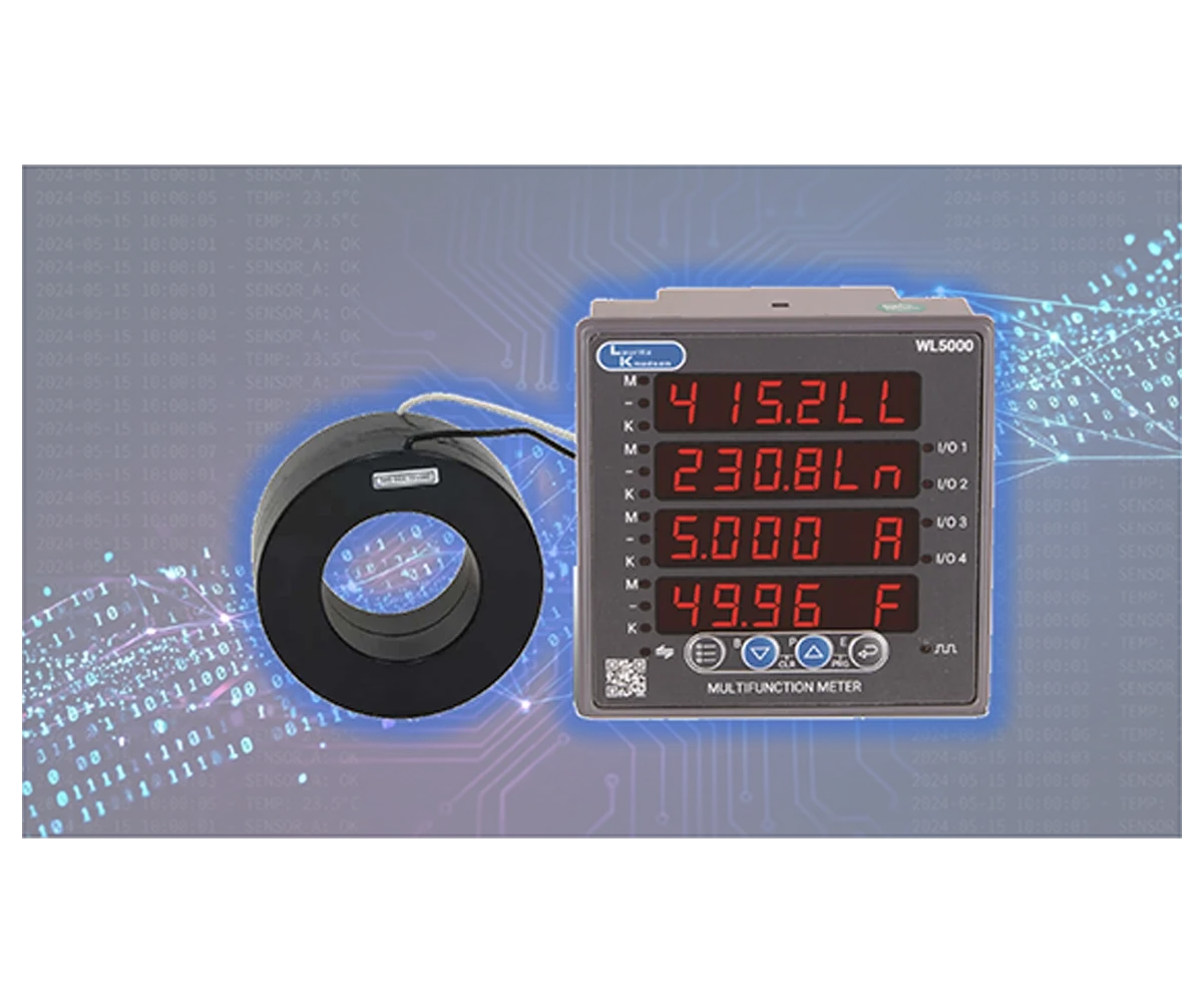
Lauritz Knudsen Electrical C Automation Digital Panel Meters have feature of Site-selectable CT and PT. This feature offers exceptional flexibility and convenience during installation and commissioning of digital meters. It allows users to configure the meter for different CT and PT ratios directly at the site without replacing hardware or recalibrating the system. This reduces installation time, eliminates the need for multiple meter variants, and minimizes inventory costs. Additionally, it ensures accurate scaling of measured values for diverse applications, from low-voltage panels to high-voltage systems, improving adaptability and reducing errors caused by incorrect ratio settings. Overall, this feature enhances operational efficiency, simplifies maintenance, and supports quick system upgrades.
Conclusion:
Accuracy classes in measuring CTs play a vital role in ensuring precise current measurement for metering and monitoring applications. Classes like 0.2 and 0.5 are suited for high-accuracy needs, while 0.5s is ideal for revenue metering due to its superior performance at low loads. Understanding these classifications helps in selecting the right CT for reliable and efficient power system operation.
Assistance Required?
Select an option to Contact Us

 Contact Us

